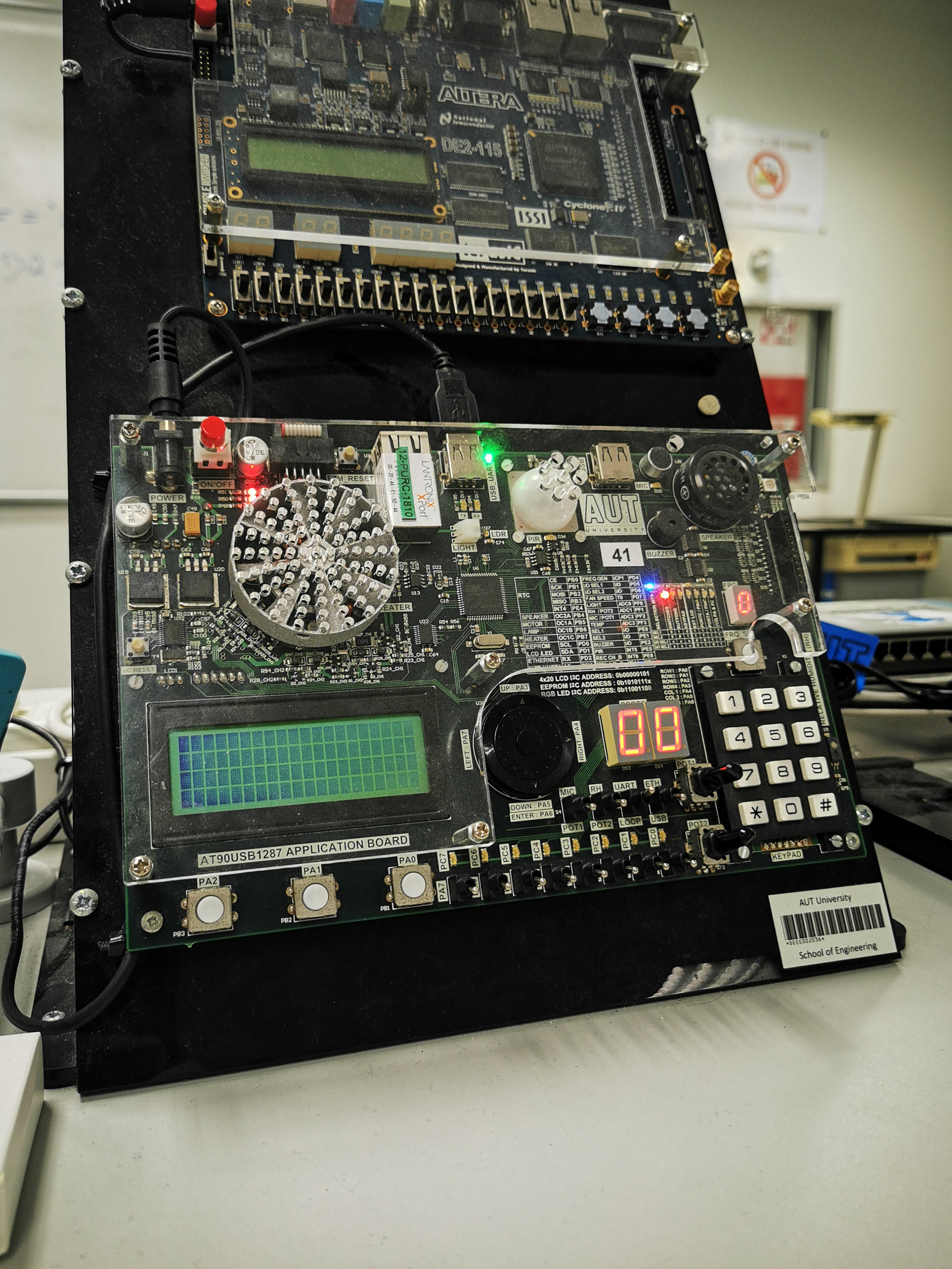
Embedded Systems Design-Project
Building an interface using Windows forms written in C# which would read and control all of the AUT lab board peripherals logging results to a MySQL database.
ENEL712 Embedded Systems Design-Project
About
This was a project I completed for ENEL712 Embedded Systems Design directed by Dr. Jack (Xuejun) Li. In this project we were to create an graphical interface using Windows forms written in C# which would read and control all of the AUT lab board peripherals. This was achieved using the USART protocol on the AT90USB to send and receive a custom byte sequence defined as part of the project requirements. Additionally, this Windows form was connected to a database for logging of time and temperature values. The heater was also controlled by a PID controller which added a little extra challenge.
Useful Resources
Before we get deep into the details, I would like to share some of the resources that I believe useful for the project:
- The official Microchip developer guide - If you’ve never programmed a microcontroller before, this should be you starting point, it will give you all the information you need in the context of programming Microchip microcontrollers.
- RealTerm: Serial/TCP Terminal - Essential for debugging your serial communications.
- Replit - Here you can create a working environment in seconds for doing some simple testing of non-hardware dependent code. Although if you’re in it for the long run I would suggest learning how to compile your c project using the command-line, following this learn CMake for more complicated builds.
Objectives
Microcontroller
The microcontroller of choice is the Atmel AT90USB1278 and is programmed in the C programming language. The program will require the ability to use a custom protocol over USART. When an instruction is received the microcontroller should perform a task and report back an acknowledgement or data. These tasks will be explained in the following sections.
Graphical User Interface (GUI)
The GUI will be a windows form application and will consist of the four following tabs:
- Serial port and database connections
- LED display and control
- Potentiometer display and lamp control
- Temperature control, display and database logging
Each of these tabs will also include open-source windows form assets such as LEDs1, gauges2 and seven-segment3 displays.
Database
Using the MySQL libraries within Visual Studio the user will be able to connect and log time and temperature data on the locally hosted server both manually and automatically. This will require the initialisation of a new user, database and table whose credentials are submitted within the GUI.
Methodology
System Design
A system design was derived from the project requirements which can be see in the diagram below:
graph LR
    style peripherals1 stroke:#ff0
    style peripherals2 stroke:#ff0
    style micro stroke:#f00

    subgraph peripherals1[Peripherals]
        p1[Switch 0-7] ~~~
        p2[LED 0-7]
        p3[LDR]
        ~~~ p4[Potentiometer 1-2]
        p5[Thermistor]
    end

    subgraph peripherals2[PWM Controlled Peripherals]
        heater[Heater]
        fan[Fan]
        lamp[Lamp]
    end

    subgraph pc[Personal Computer]
        winForm[Windows Form]
        database[(MySQL Database)]
    end

    subgraph micro[AT90USB]
        timer[16-bit Timer]
        usart[USART]
        gpio[GPIO]
    end

    subgraph labboard[AUT Lab Board]
        peripherals1
        peripherals2
        micro
    end

    peripherals1 <--Set/Read--> gpio
    peripherals2 <--PWM--> timer
    usart <--Custom Protocol--> winForm
    winForm --> database
Board Bringup
As with most microcontroller projects, I started with getting a simple LED to turn on, developed in Microchip Studio. Starting with the bare minimum ensured that my environment was setup correctly. This looked something like the following:
1
2
3
4
5
6
7
8
9
10
11
12
13
14
15
16
17
18
19
20
21
22
23
24
25
26
#include <avr/io.h>

#define ledOn (PORTC |= (1 << 0))
#define ledOff (PORTC &= ~(1 << 0))
#define switchIsOn (PORTA & (1 << 0))

void setup(void);

int main(int argv, char *argc[]) {
    setup();
    for(::) {
        if (switchIsOn) {
            ledOn;
        } else {
            ledOff;
        }
    }
    return 0;
}

void setup(void) {
    DDRC = 0xFF; // set output - leds
    DDRA = 0x00; // set input - switches
    DDRE = 0x03; // set output - multiplexer for switches
    PORTE = 0x00; // set multiplexer value
}
Modular Structure
Using standard programming practices such as having the project modular by keeping groups of related functions in their own associated .cpp and .h file. The .h file would contain libraries, macros, variable declarations, structures and function prototypes. This ensures that the project is maintainable and easy to understand. Below is an example .cpp and .h pair, which represent a reusable module:
1
2
3
4
5
6
7
8
9
10
11
12
13
14
15
#ifndef EXAMPLE_HEADER_H
#define EXAMPLE_HEADER_H

// libraries
#include <avr/io.h>

// macros
#define ledOn (PORTC |= (1 << 0))
#define ledOff (PORTC &= ~(1 << 0))
#define switchIsOn (PORTA & (1 << 0))

// functions prototypes
void turnLedOn(void);

#endif // EXAMPLE_HEADER_H
With the implementation details in the .c file:
1
2
3
4
5
6
7
8
9
10
#include "example_header.h"

void turnLedOn(void) {
    if (switchIsOn) {
        ledOn;
    } else {
        ledOff;
    }
}
Usart.h
One of the project requirements was to use a given custom protocol which was sent over USART. This is shown in the following diagrams where each block represents a byte:
Set Peripheral
block-beta
    block
        columns 5
        start instruction msb lsb stop
    end
block-beta
    block
        columns 1
        instruction
    end
Read Peripheral
block-beta
    block
        columns 3
        start instruction stop
    end
block-beta
    block
        columns 1
        data
    end
The strategy use for the custom protocol was to have a global pointer to a struct serialCom_t which held all of the necessary variables for the communication. This and explanations of each of the variables can be seen below:
1
2
3
4
5
6
7
8
9
10
11
12
13
14
#define BUFFER_LEN 5
enum UsartState_t { IDLE, READ };
enum InstReady_t { FALSE, TRUE };

struct serialCom_t {
    char buffer[BUFFER_LEN];                // [start][inst][msb][lsb][stop]
    char* p_buffer;                         // keep track of current buffer position
    enum UsartState_t state;                // waiting for start byte (IDLE) or READ state
    enum InstReady_t instruction_ready;     // instruction is read to execute
    char instruction;                       // the current instruction
    int data;                               // msb and lsb recombined
};

volatile struct serialCom_t* p_serialCom;   // the global struct, volatile because it is accessed during ISR
Basically how I would use this is that once an interrupt happens on the RX buffer of the USART, the program would check for a start byte (0x53). When this happen the serial comms state goes into read mode and reads all of the expected bytes into the buffer. I somewhat cheated here, rather than checking for a stop by a just made an assumption that the protocol would always send through all five bytes. However, we can see from the diagram above that the read instruction only sends three bytes. Which is fine, because it will never use any of the bytes after the instruction byte on a read request:
1
2
3
4
5
6
7
8
9
10
11
12
13
14
15
16
17
18
19
20
21
22
23
void readUsart(void) {
    // read in the next byte
    *(p_serialCom->p_buffer) = UDR1;

    switch (p_serialCom->state) {
        case IDLE: // wait till start byte
            if (*(p_serialCom->p_buffer) == START_BYTE) {
                p_serialCom->state = READ;
                *(p_serialCom->p_buffer) = 0; // clear start byte
                p_serialCom->p_buffer++;
            }
            break;
        case READ: // save all data to buffer
            p_serialCom->p_buffer++;
            if (p_serialCom->p_buffer ==
                &p_serialCom->buffer[4]) { // end of buffer, reset
                p_serialCom->p_buffer = p_serialCom->buffer;
                p_serialCom->instruction_ready = TRUE;
                p_serialCom->state = IDLE;
            }
            break;
    }
}
Once all of this is done we can see the instruction_ready member is set to true, which then allows the execute instruction function in the main method to execute:
1
2
3
4
5
6
7
    // main loop
    for (;;) {
        if (p_serialCom->instruction_ready) {
            saveBuffer();
            exeInst();
        }
    }
Where execute instruction is just a switch statement for each instruction which basically sets or reads a peripheral and resets all the variables, ready to go again. The benefit of this is that if another byte were to be read in during the execution of the instruction, it wouldn’t interfere as we have extracted the contents of the buffer.
1
2
3
4
5
6
7
8
9
10
11
12
13
14
15
16
17
18
19
20
21
22
void exeInst(void) {
    switch (p_serialCom->instruction) {
        // read instructions
        case TX_CHECK:
            sendUsart(TX_CHECK);
            break;
        case READ_PINA:
            sendUsart(PINA);
            break;
        case READ_POT1:
            sendUsart(getAdcValue(POT1));
            break;
        //...
        // the rest of the instructions
        //...
    }
    // reset values
    p_serialCom->data = 0;
    p_serialCom->instruction = NONE;
    p_serialCom->instruction_ready = FALSE;
}
Overall this was great fun to work on. Another advantage of using CMake as recommended at the start, is that we can use the set(CMAKE_EXPORT_COMPILE_COMMANDS ON) which when used with the clangd language-server from clang-tools will give you much better error messages than what microchip studio gives. This is slightly advanced, but I believe you can get the same outcome with popular c/c++ plugins within vscode.
Windows Form
The Windows form functionality found in Microsoft Visual Studio was used to build the GUI. This used events and event handlers to handle user interaction. All the elements in the form toolbox were drag and drop which also included the automatic generation of event handlers. Example event handlers can be seen below:
1
2
3
4
5
6
7
8
9
10
11
12
13
14
private void PortNamesBox_Clicked(object sender, EventArgs e)
{
    UpdatePortNamesBox();
}

private void ComPortBox_SelectedIndexChanged(object sender, EventArgs e)
{
    _labBoard.setComPort(ComPortBox.Text);
}

private void BaudBox_SelectedIndexChanged(object sender, EventArgs e)
{
    _labBoard.setBaudrate(Convert.ToInt32(BaudBox.Text));
}
Once the GUI had been formatted using the drag and drop system, it was then a matter of programming each of the form elements’ interactions and functionalities. This was done using a separate LabBoard class which was the API for interfacing with the lab board. Starting with the LED tab it was first ensured that when an instruction was sent, that the correct reply was received. Once this was completed it was simply a matter of repeating this for other functionalities, relying heavily on the debugger in both the C and C# program to understand the flow of data. Asynchronous read and write commands were implemented so that the application was not held up while waiting for the correct response from the lab board. Example API entries can be seen below:
1
2
3
4
5
6
7
8
9
10
11
12
13
14
15
16
17
18
19
20
21
public async Task<int> readLamp()
{
    return await readUInt8(instruction: READ_LAMP);
}

public async Task<int> readTemp()
{
    return await readUInt8(instruction: READ_TEMP);
}

public async Task<bool> writePortC(byte data)
{
    int reply = await writeUInt16(instruction: SET_PORTC, data);
    return (reply == SET_PORTC);
}

public async Task<bool> writeLamp(UInt16 data)
{
    int reply = await writeUInt16(instruction: SET_LIGHT, data);
    return (reply == SET_LIGHT);
}
The last tab implemented the graphing of data, database data logging and the PI portion of a PID controller for temperature control. Pseudo code was found on Wikipedia4 in order to implement the PID control. Suitable prototyping values were found after some experimental adjustment. The correct values for scaling the temperature were found in the lab-board schematic being 50mV/°C with a max of 80°C and therefore the calculation in (1) shows the maximum voltage from the temperature sensor.
\[\begin{equation} 50mV \times 80 = 4\% \label{eq:1} \end{equation}\]Because the max input voltage to the ADC was 5.15V this allowed the calculation of the percentage of max temperature reading in volts to the max ADC input (2). From this the maximum digital value for the temperature was found with equation (3).
\[\begin{equation} \frac{4}{5.15} = 78.125\% \label{eq:2} \end{equation}\] \[\begin{equation} 0.78125 \times 256 = 200 \label{eq:3} \end{equation}\]Following this, the equation (4) was developed to convert to and from the digital reading
\[\begin{equation} \frac{T_{digital}}{200}=\frac{T_{Celsius}}{80} \label{eq:4} \end{equation}\]Database Integration
Xampp5 was used for the local server which uses Apache and MySQL. This was setup using a YouTube guide6 which showed how the MySQL library functions worked and how to connect to a local server. A password protected account with read and write privileges was created so that it could issue SQL queries. A new database and table were also made, which then made it possible to use the MySQL library functions to connect to the server and upload some test data. Once this was achieved it was simply a matter of automating the data-logging process connecting it to the timer event handlers.
Results
Overall the finished project worked well and met all of the requirements. There were some cases such as checking that the user is connected before allowing them to change tab that were not considered, this would be considered in the next version if there were one. The resulting c code can be found here and accompanying c# code can be found here. If you’ve made it this far, thank you for reading.
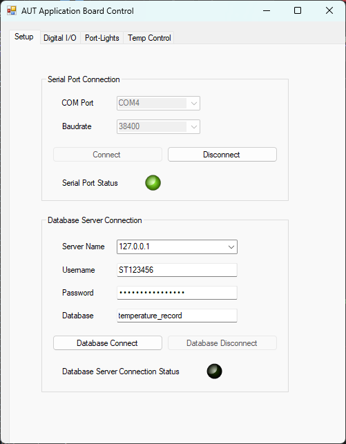 Tab 1: Serial Port and Database Connection
 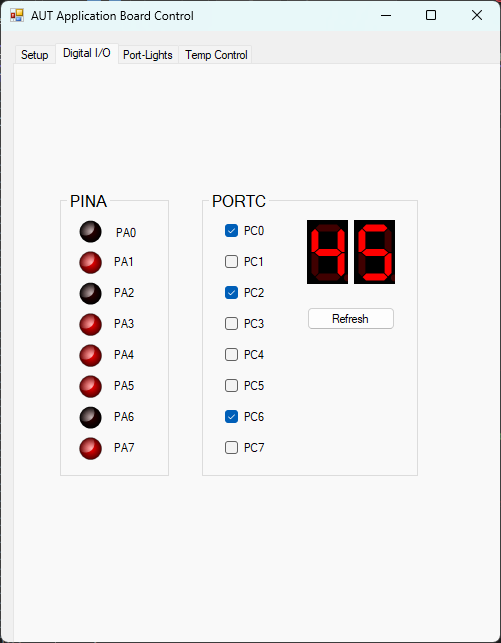 Tab 2: Led Control
 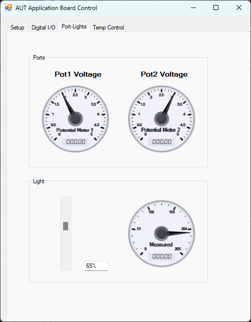 Tab 3: Lamp Control and Potentiometer Readings
 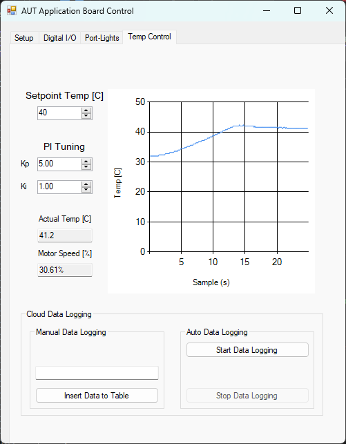 Tab 4: PID Controlled Heater
References
S. Marsh, A Simple Vector-Based LED User Control, CodeProject. (accessed May 08, 2023). ↩︎
A. Thirugnanam, Aqua Gauge, CodeProject, Sep. 04, 2007. (accessed May 08, 2023). ↩︎
D. Brant, Seven-segment LED Control for .NET, CodeProject, Jul. 01, 2009. (accessed May 08, 2023). ↩︎
PID controller - Wikipedia. (accessed May 08, 2023). ↩︎
XAMPP Installers and Downloads for Apache Friends. (accessed May 08, 2023). ↩︎
How to connect phpMyAdmin MySQL Database in Visual Studio .NET Core C# Windows Form Application - YouTube’ (accessed May 08, 2023). ↩︎
